January 31, 2017: 3D Printer Remote Relay Setup
Wecome! To a tutorial on how to connect a relay to your RaspberryPi running OctoPi and remotely turn your 3D printer on/off. Without having to splice your OEM cord!
Materials to start this project:
- 3D Printer
- RaspberryPi (running OctoPi)
- SainSmart Relay (4-CH)
- Extension Cord (really depends on needs)
- Outlet
- Electrical Box
- Outlet Panel
- NM/SE Connector
- A Wire Nut
- Screwdriver
- Wire Cutters
- An extra 6"+ 14-16 gauge stranded wire (cut from extension cord)
- Heatshrink Tubing
- Soldering Iron
- Printed VESA mounts
- 6 F-to-F Jumper Wires
- M3 .05" x 10 screws/nuts x4
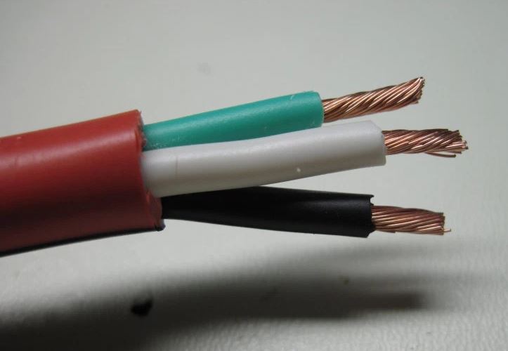
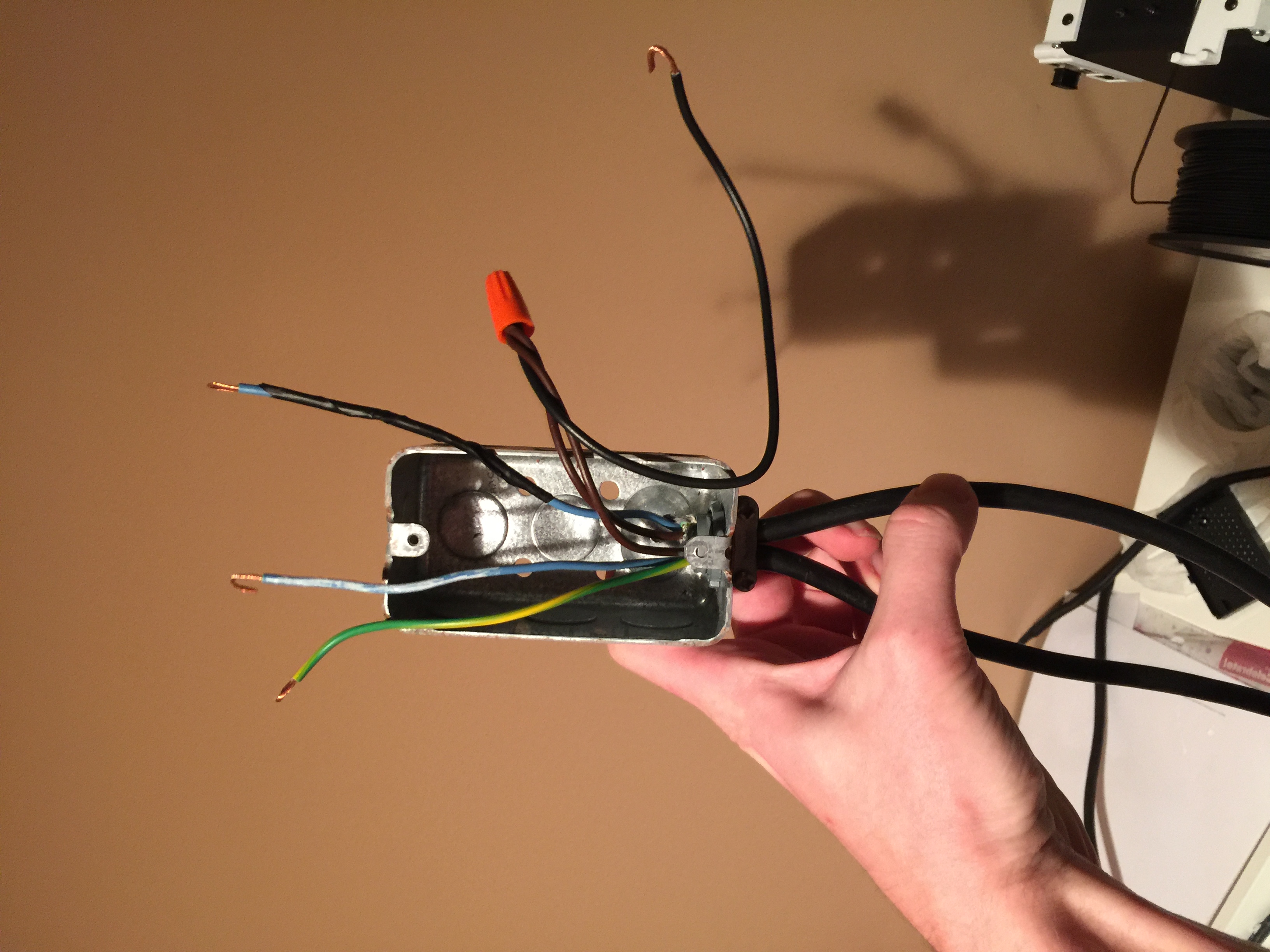
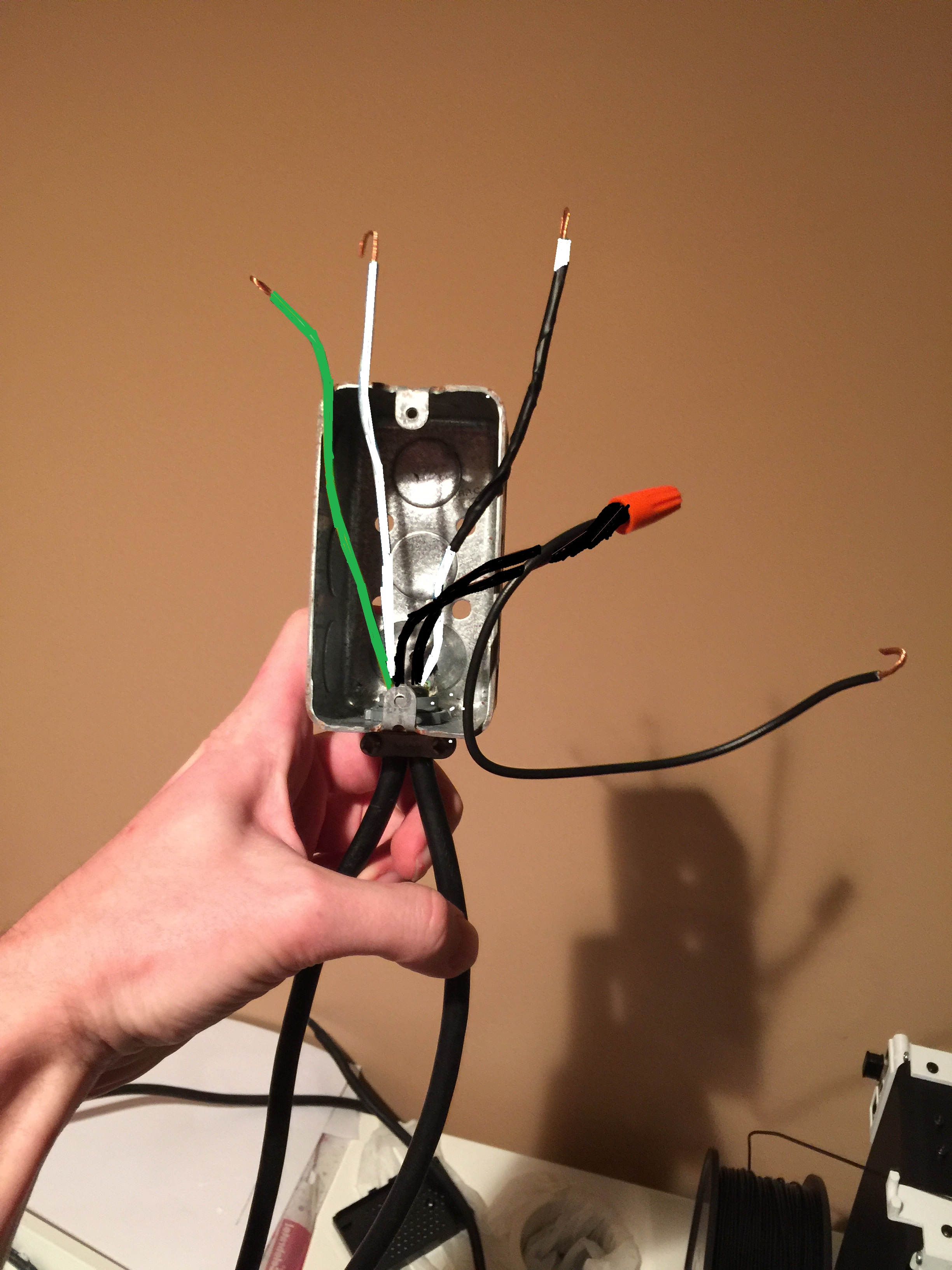
I just recently bought a Monoprice Select Mini 3D printer for $170, and just started getting into 3D printing. Within a day or two, I stumbled across the RPi OctoPi image. I was really happy to find out about this because I was having a lot of stopping mid-print issues with the SD card, and homing itself and starting over. Setting it up was cake, plenty of good information on their webpage. I didn't like how I would still have to go over and turn the knob to change the speed, until I found out I could add options in the "Control" tab. Finally, the last step I intended to add to OctoPi was a remote on and off for the printer, which brings us to the beginning of this tutorial. I would like to point out beforehand that my WIRE COLORS MAY BE DIFFERENT than yours. I tried using electrial tape, and white paint marker where I could to help cordinate with standard US colors (Black(Hot), White(Neutral), Green(Ground)). I used a spare extension cord lying around that happen to use UK colors (Brown(Hot), Blue(Neutral), Grn/Ylw(Ground)).
Part One: Printing and Mounting
- Print yourself the back vesa mount for the Monoprice Select Mini, and also print my mount for the relay while you're at it.
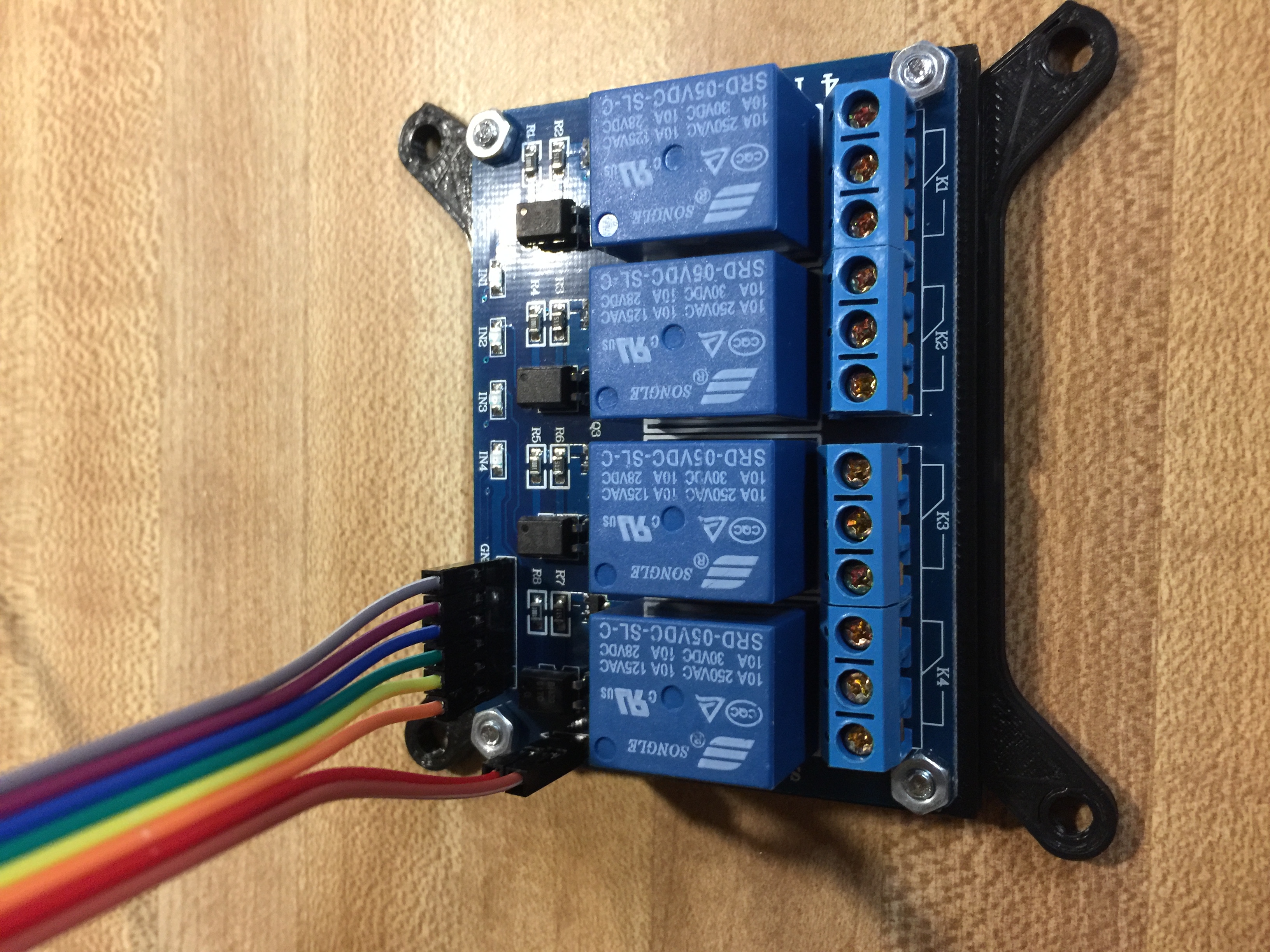
- Once printed, go ahead and attach the relay to my mount using M3.05x10 screws and M3 hex nuts (x4). At this point you can also go ahead and attach your 6 female jumper cables to the relay board. Once I put mine in place, I chose to hot glue them together so they pulled out in once piece. You don't have to do that it's just an option.
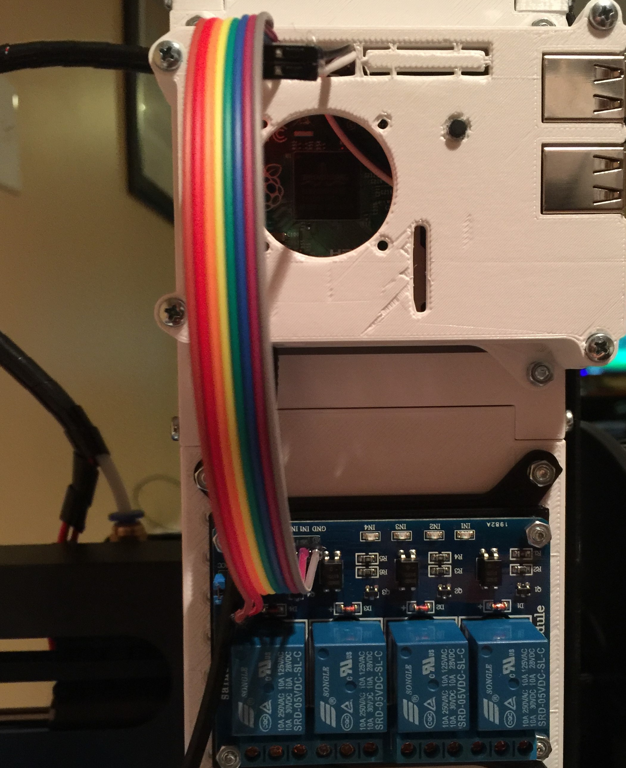
- Screw your 9H back mount under your Pi and attach the other ends of your 6 female jumpers to it. MAKE SURE YOUR PI IS OFF!!
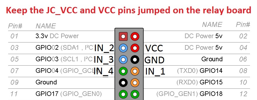
- VDD -> 5v on Pi
- GND -> GND on Pi
- IN1 -> GPIO14 on Pi
- IN2 -> GPIO02 on Pi
- IN3 -> GPIO03 on Pi
- IN4 -> GPIO04 on Pi
- Reference Image
Part Two: Quick Coding Section
- SSH into your RPi using your favorite tool, I like PuTTy it's easy to use.
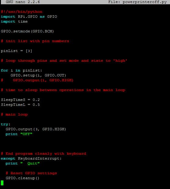
- The Octopi image already has a scripts folder, so I wrote the on/off scripts in that folder because it only made sense. So navigate there by typing "cd scripts/" then type "sudo nano powerprinteron.py" and make sure you type this code in there. Save your file with Ctrl+X, Y, enter. Then type "sudo nano powerprinteroff.py" and make sure this code goes there. Save your file and return to the main user directory by typing "cd".
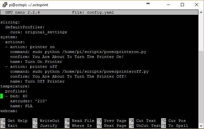
- Navigate to OctoPi's config file by typing "cd ./octoprint" then type in "sudo nano config.yaml".
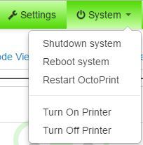
- Scroll down the config file until you see the System section of it. Type this in that section. Once you've typed it in, save and overwrite your changes. If you open your OctoPi webpage and restart the service you'll see the two options you just created under System on the top bar. (This is only seen logged in as an Admin)
Part Three: The Fun Part! Wiring and Stripping
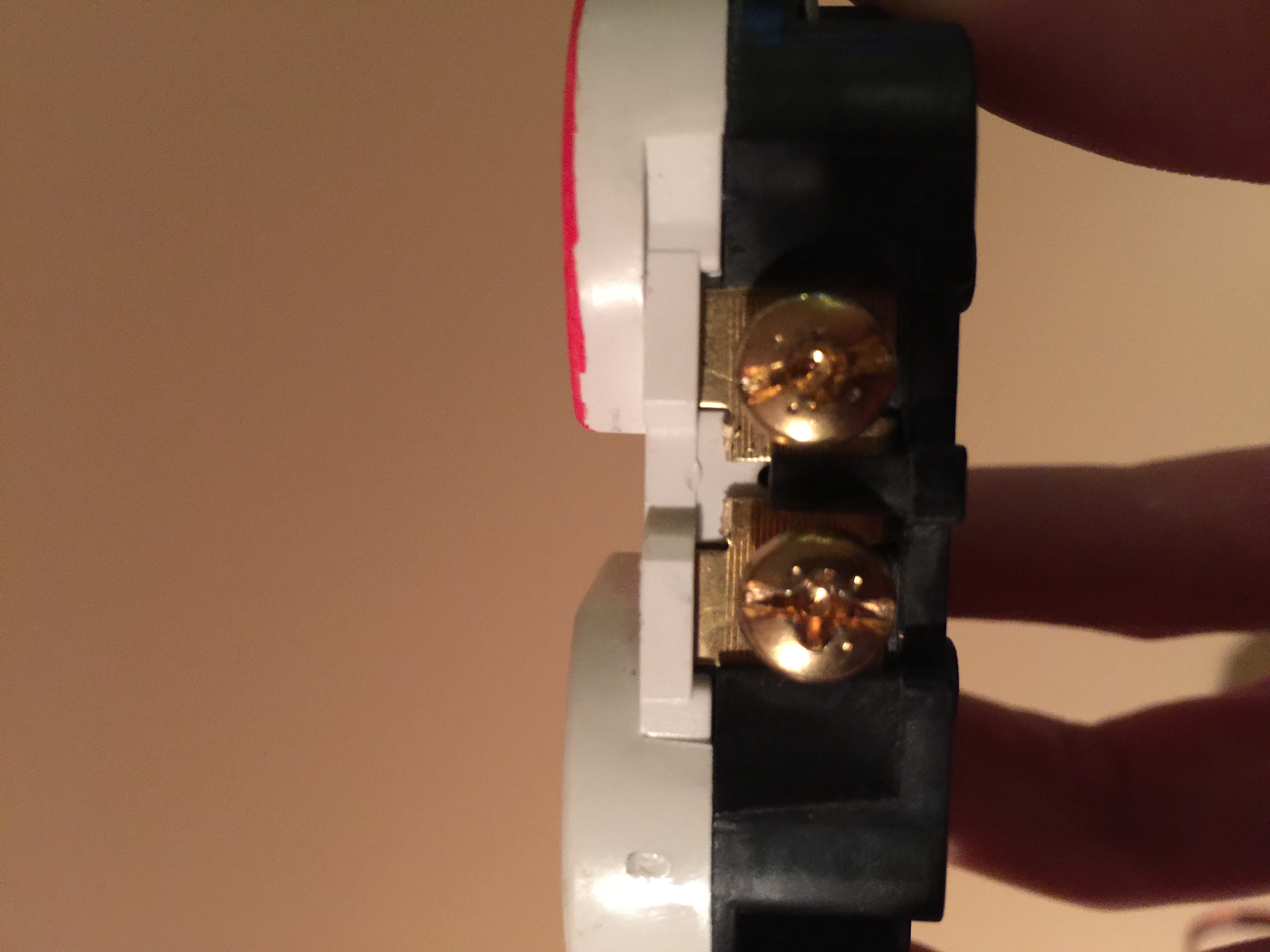
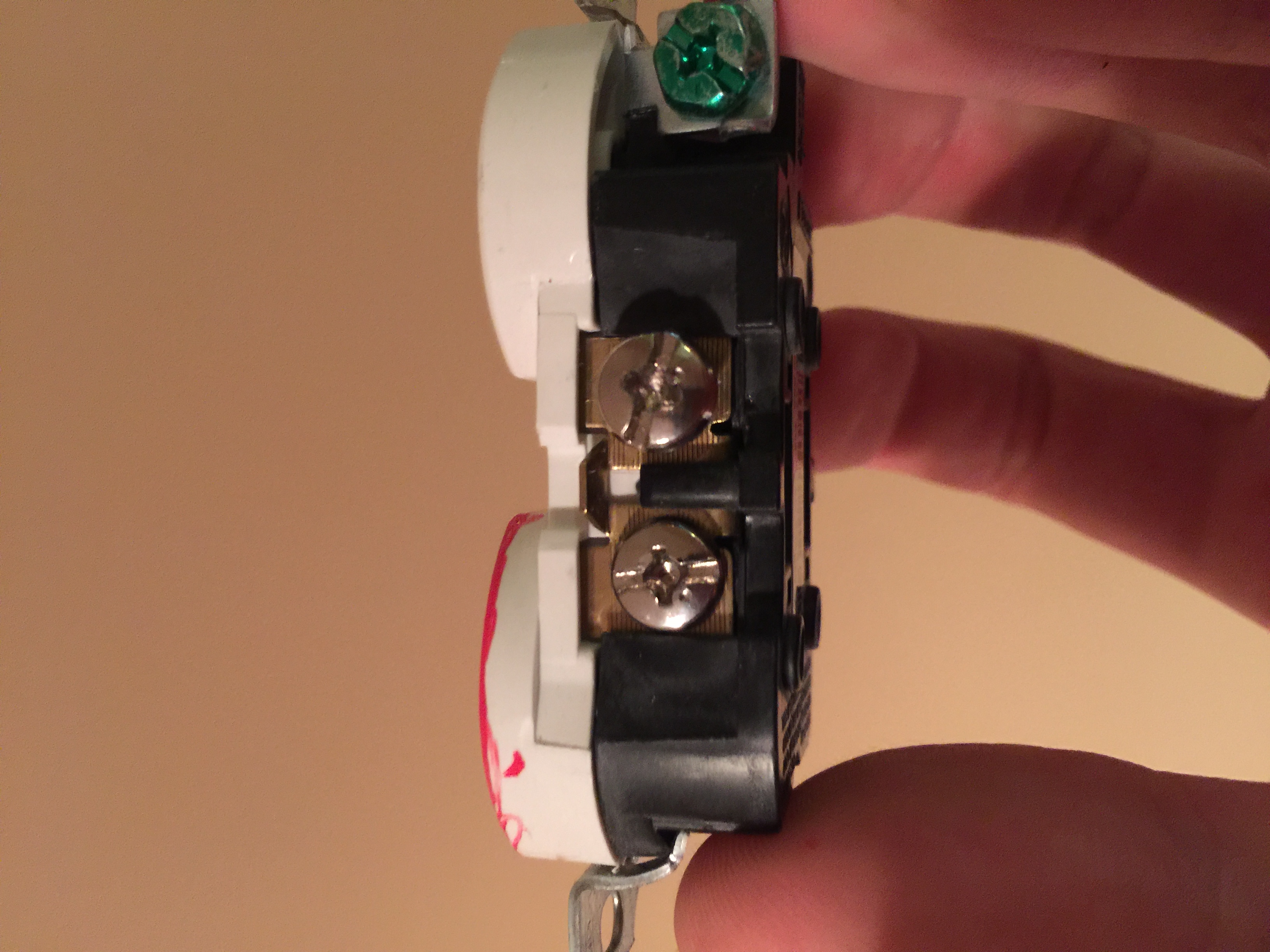
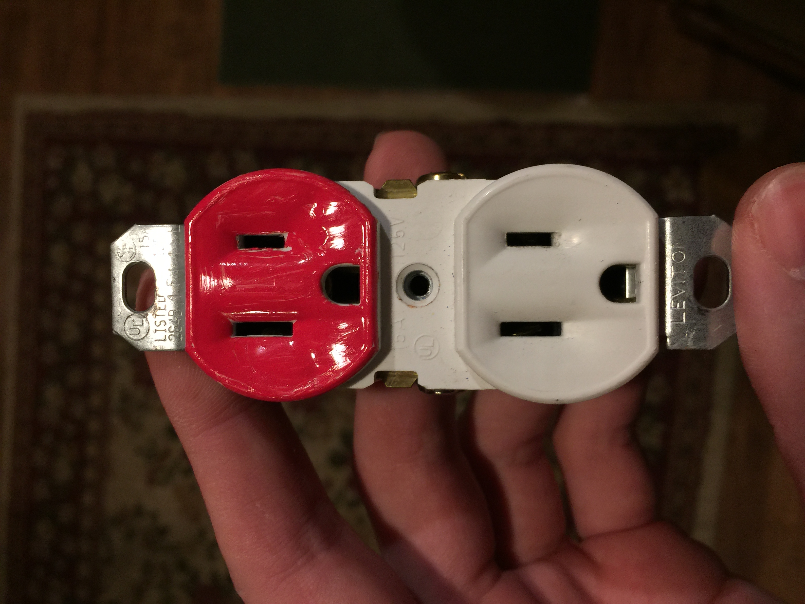
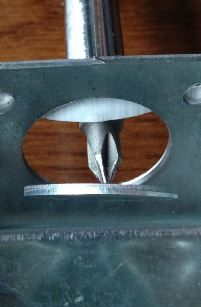
- Grab the outlet you picked up and take a look at it. One side has gold screws, and the other side has silver screws, and has the green ground screw as well. We want to BREAK the tab between the gold side, which is the HOT (black wire) side of the outlet. We want to KEEP the tab together on the silver side, which is the Neutral (white wire) side. What does breaking the tab do you ask? Well normally, that bridges the connection so that both outlets work, with only 1 hot and 1 neutral attached. In this case, we are making an outlet box that will have power always on the bottom (for our Pi), and the top outlet will be switched on and off by our relay. I went ahead and marked mine with a red paint marker. Set aside
- Pick up the electrical box you purchased, and pop out one of the holes on the top or bottom. They are attached with a small piece of metal, and do need some force to puncture. Once you've got that punched out, and have your hole, insert and screw your NM/SE connector into place. Set aside
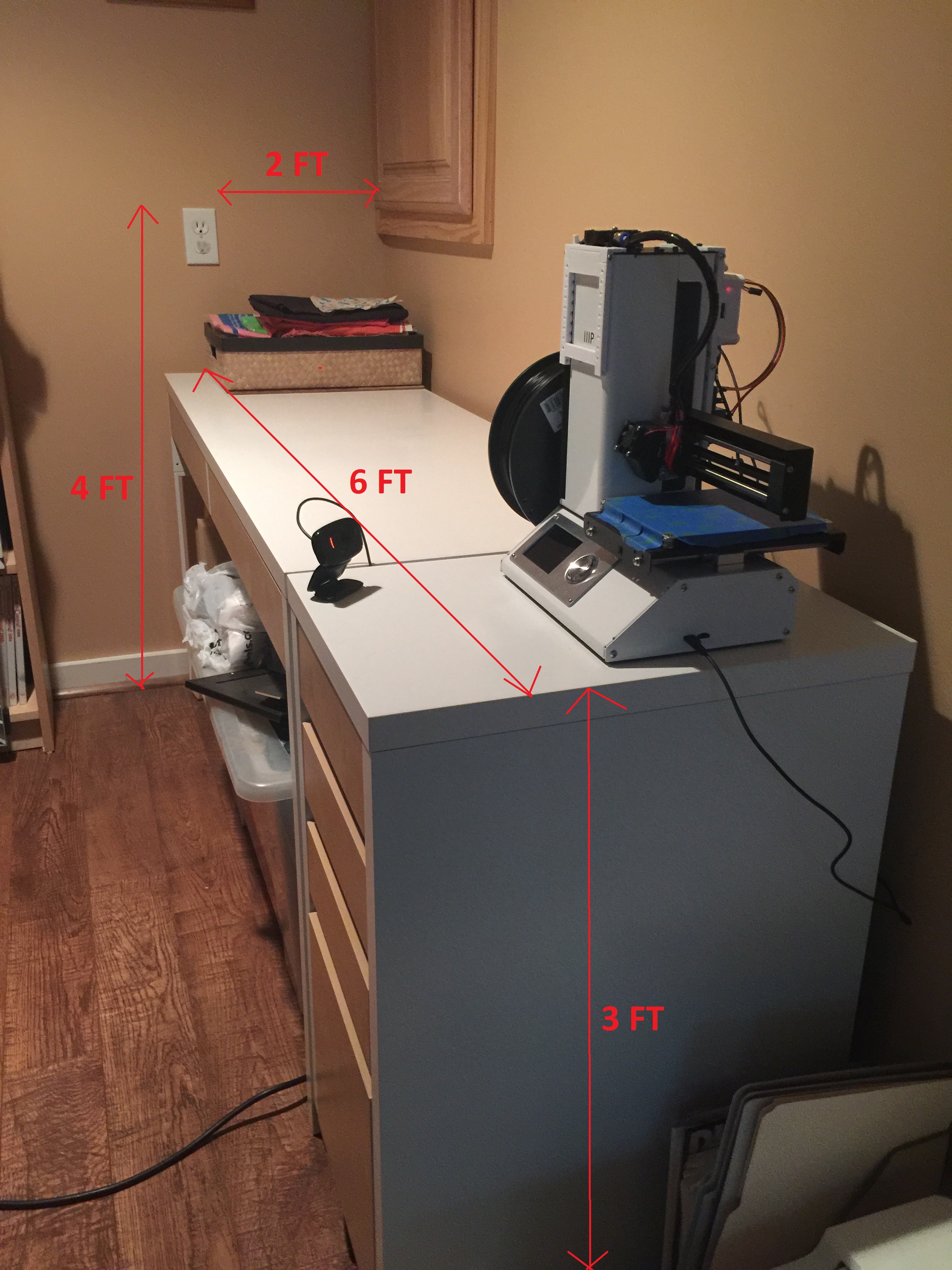
This is where the length of cord depends on your requirements (My example application). As you can see, I needed about 15ft of extension cord. However, that isn't factoring in the extra 6" piece stranded wire we need. This is why I would suggest BUYING 5FT OVER what you need, so that you have plenty of extra, and some room for mistakes/errors. Now that's out of the way we can proceed.
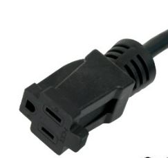
- Snip the female end of the extension cord off as close as you can get it. Once that is snipped, go ahead and measure aprx. 6"- 8" down the cord, and cut it there. We only need the black wire from the small piece you just cut, so go ahead and pull the black wire out from the shielding. Strip both ends of that black wire, and twist the strands in a clockwise motion and set it aside. (Whenever I say strip, please know I expect you to twist them after so every wire you strip looks like this.)
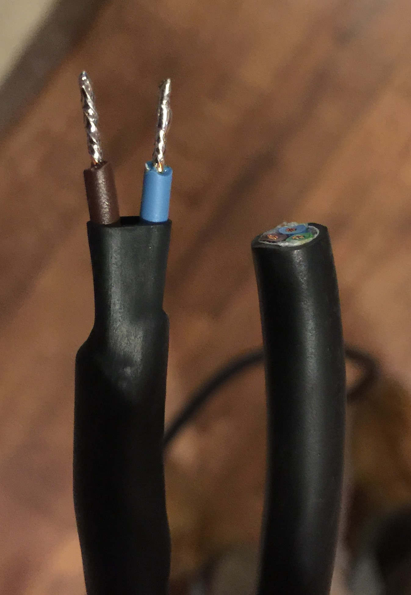
- Measure the length of extension cord that will be running from the relay to the the outlet. In my example link above, you can see my measurement was about 3FT of cord from relay to the floor where the outlet will be sitting. Cut your length of extension cord, from the side you already have cut. Remove some shielding from the wires so that you have the 3 wires exposed. We only need 2 of these wires, which BOTH will back acting as HOT (the black wire). So to make sure I knew which was to be the cord that went from the printer to the outlet, I cut the ground wire down, so that you only saw two wires. Strip both remaining wires, and solder the tips. Once soldered, apply some heatshirnk tubing to bring it all together. It should look something like this!
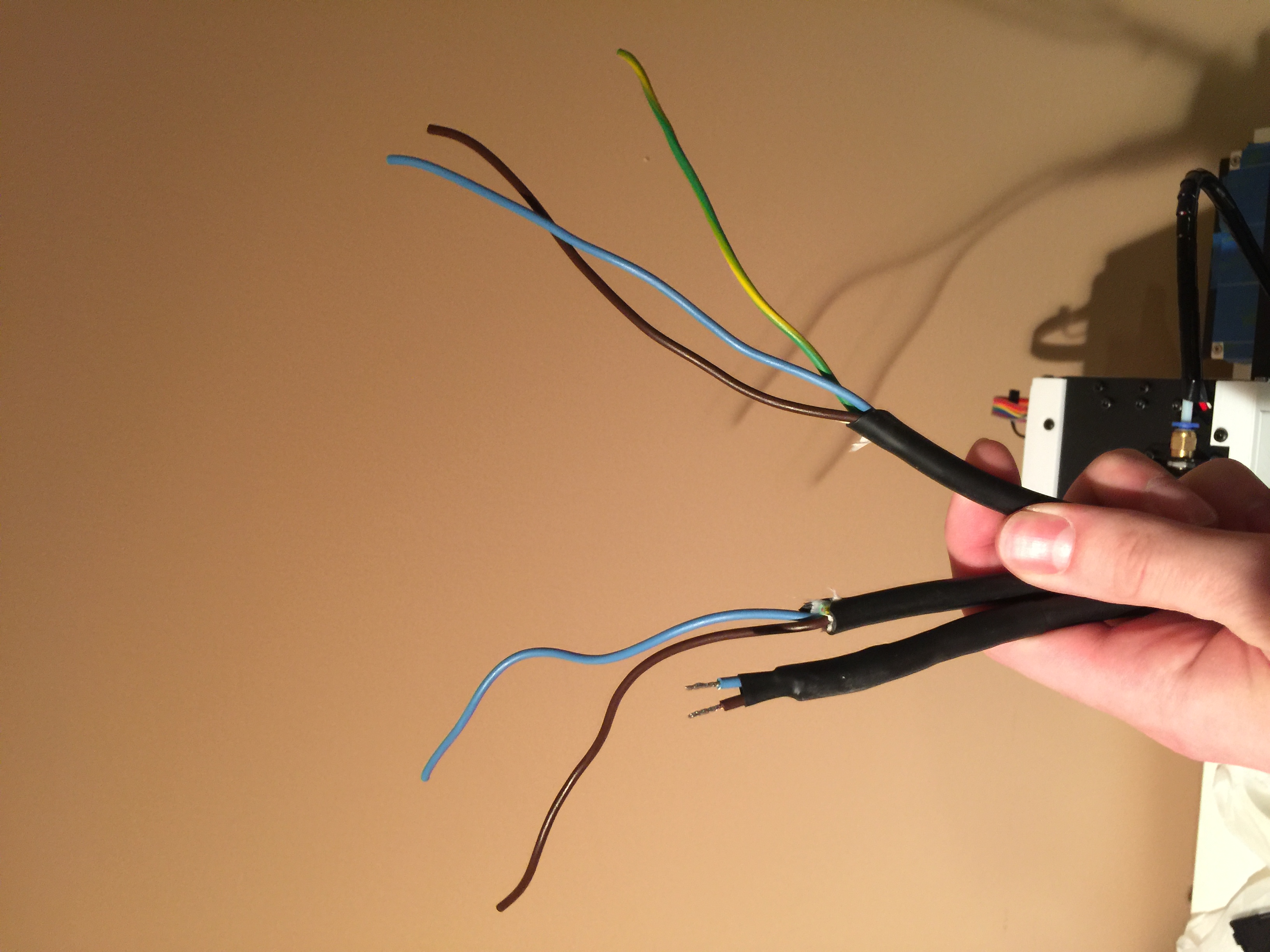
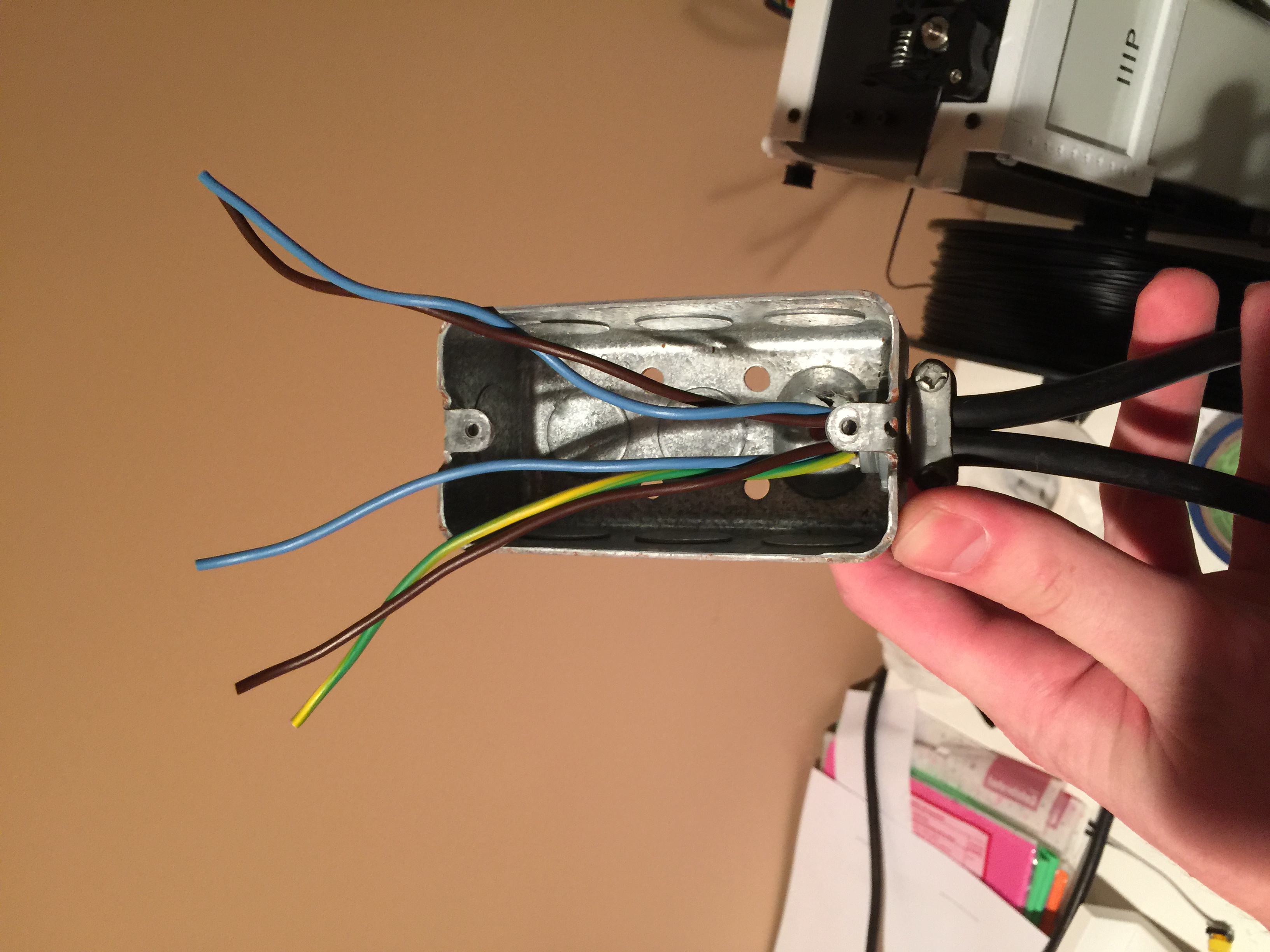
- Now we want to strip the remain ends of the wire we have left. So, the short wire, which you just soldered, needs the sheilding pulled away on the opposite end, and those wires need to be stripped. After that, you'll want to do the same thing to the end of your remaining long extension cord. What you should have looks like this. The wire to the left of my thumb is the short length you cut for the relay to outlet were making. The cord to the right of my thumb, is the long remaining length that will be plugged into the wall outlet. Once you have them stripped and ready like that, you can pick up your electrical box, and secure the wires into the box. It should look like this now. Now that everything is secure it's time to add our last wire. Pickup your small 6-8" length of black wire I had you put down earlier. Twist that wire in with the two HOTs(black wires),securing them together with a wire nut. If that picture is confusing since my colors are different I hope this helps. (Remember the White Wire with the black tape is acting as a HOT, that's why I have it taped black, to help myself identify while wiring)
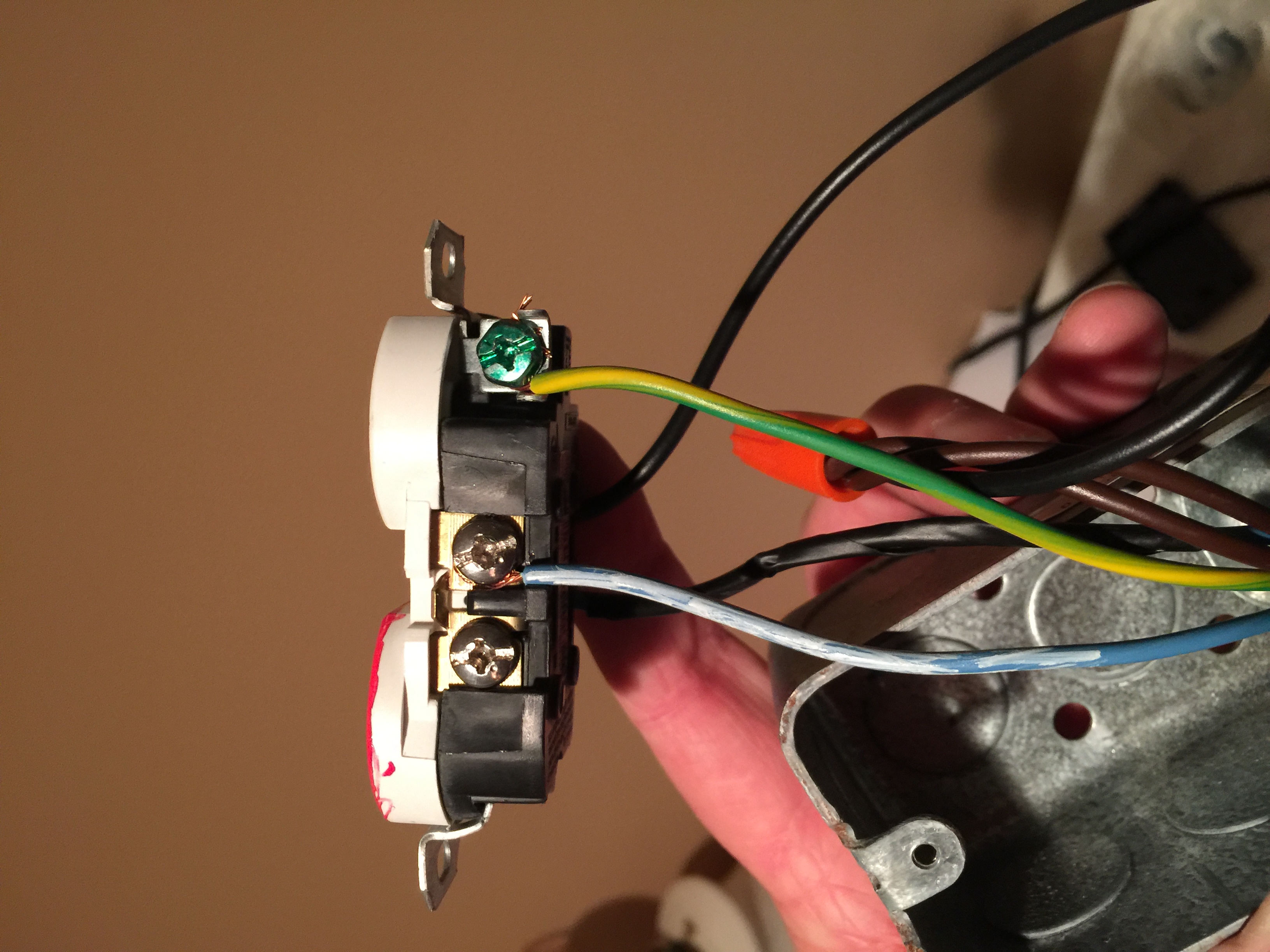
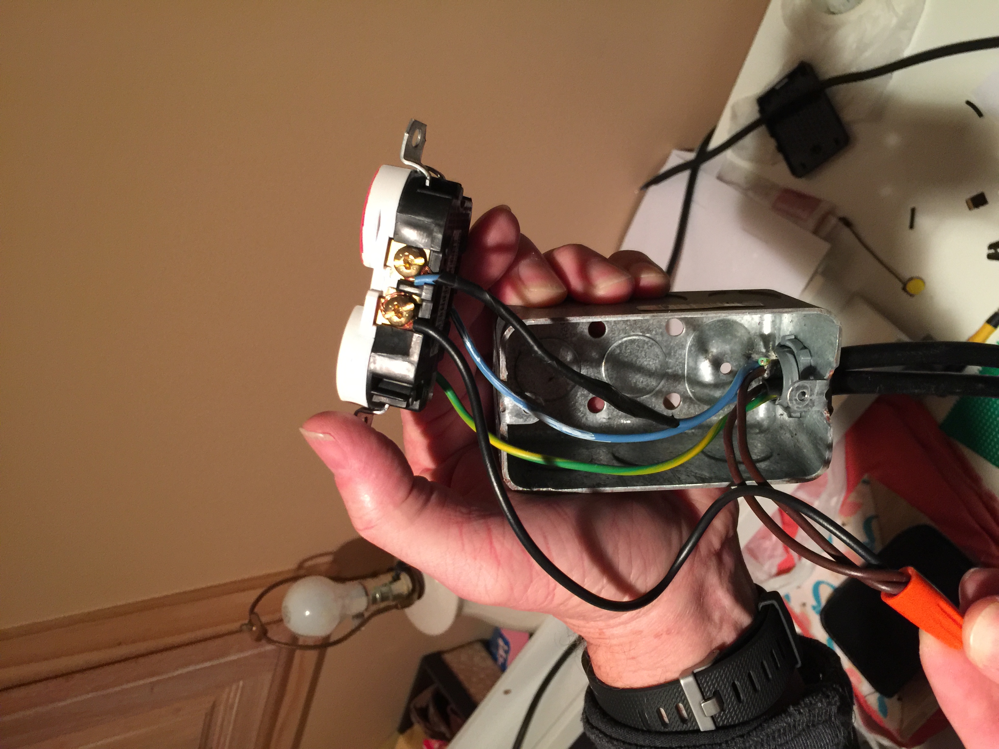
- We're ready to wire everything to the outlet and get this project finished! You can go ahead and pickup your outlet you marked earlier. Lets start with the Neutral(silver screw) side. Since we didn't break that sides tab, it doesn't matter which screw you tighten your wire too, but fasten the ALL white wire to it, and fasten the Ground(green screw and green wire) to the outlet as well. Now we only have two wires left! They are both HOT(gold screw) side, but are different colored wires. This part is important on which wires go to what screw, since we painted an outlet to be switched by the relay, and broke the tab between the outlets. The ALWAYS HOT wire, which is connected in with the WIRE NUT, should be fastened to the NOT PAINTED outlet. This makes sure that outlet is always live power, and not switched (for our RPi power supply). The remaining white wire (marked black) that we are using as a HOT, gets fastened to the remaining screw. At this point your done! Push all your extra wire down into the box, and screw your outlet to the box, and attach the face plate.
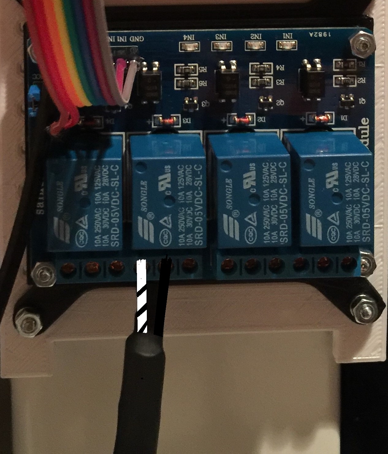
- Lastly, all you need to do is attach your two soldered ends of wire to the back of the relay. In the script you copied, I used relay IN3, so if you want it to work without changing the script, attach your wires to IN3 on the relay. Notice the relay has 3 inputs. You use the far left inputs, attaching the actualy black wire to the middle, and the white (acting as black) to the left of it. It should look like this!